Two winding transformer
Attributes, Units and Remarks
Input and Result Attributes and Units are defined at PowerSystemDataModel. Please refer to:
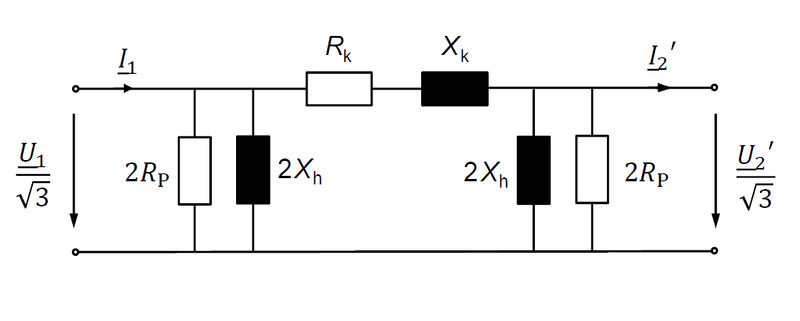
Calculation of basic equivalent circuit elements
… based on derived values. All values are given with regard to the high voltage side.
Reference Impedance: \(Z_{Ref}=\frac{V^{2}_{Ref}}{S_{Ref}},Z_{Ref}=\Omega\) based on externally given reference voltage \(V_{Ref}\) and reference apparent power \(S_{Ref}\)
Reference Impedance regarding the transformer’s reference system: \(Z_{Ref,Transf} = \frac{V^{2}_{HV}}{S_{Rated}}, [Z_{Ref,Transf}] = \Omega\)
Reference Current:\(I_{Ref,Transf} = \frac{S_Ref,Transf}{\sqrt{3} \cdot V_{HV}}, [I_{Ref,Tranf}] = A\)
Short circuit impedance: \(Z_{SC} = v_{SC} \cdot Z_{Ref,Transf}, [Z_{SC}] = \Omega\) with \([v_{SC}] = \%\)
Short circuit resistance:\(R_{SC} = \frac{P_{C_{u}}}{3 \cdot I^{2}_{Ref,Transf}}, [R_{SC}] = \Omega\)
Short circuit reactance: \(X_{SC} = \sqrt{Z^{2}_{SC} - R^{2}_{SC}}, [X_{SC}] = \Omega\)
Main field impedance: \(Z_{M} = \frac{V_{HV}}{\sqrt{3} \cdot i_{noLoad \cdot I_{Ref,Transf}}}, Z_{M} = \Omega\)
Main field resistance: \(R_{M} = \frac{V^{2}_{HV}}{P_{F_{e}}}, [R_{M}] = \Omega\)
Main field reactance: \(X_{M} = \frac{1}{\sqrt{\frac{1}{Z^{2}_{M}} - \frac{1}{R^{2}_{M}}}}, [R_{M}] = \Omega\)
When the load flow calculation asks for the values with regard to the low voltage side, each Impedance has to be divided by square of the transformers default transmission ration \(\gamma = \frac{V_{HV}}{V_{LV}}\):
Short circuit resistance: \(R_{SC,LV} = \frac{R_{SC}}{\gamma^{2}}\)
Short circuit reactance: \(X_{SC,LV} = \frac{X_{SC}}{\gamma^{2}}\)
Main field resistance: \(R_{M,LV} = \frac{R_{M}}{\gamma^{2}}\)
Main field reactance: \(X_{M,LV} = \frac{X_{M}}{\gamma^{2}}\)
Finally, all values are delivered as per unit-values and ready to use in the fundamental \(\pi\)circuit:
Short circuit conductance: \(g_{ij} = \frac{Z_{Ref}}{R_{SC}}\)
Short circuit susceptance: \(b_{ij} = \frac{Z_{Ref}}{X_{SC}}\)
Phase to ground conductance: \(g_{0} = \frac{Z_{Ref}}{2 \cdot R_{M}}\)
Phase to ground susceptance: \(B_{0} = \frac{Z_{Ref}}{2 \cdot X_{M}}\)
If there is a tap changer, this has to be taken into account as well:
Tap ratio:\(\tau = 1 - (t_{actual}-t_{neutral}) \cdot \frac{dV}{100}\)
Tap changer is on low voltage side:
Short circuit conductance: \(g_{ij} = \frac{Z_{Ref}}{R_{SC}} \cdot \tau\)
Short circuit susceptance: \(b_{ij} = \frac{Z_{Ref}}{X_{SC}} \cdot \tau\)
Phase to ground conductance: \(g_{0} = \frac{Z_{Ref}}{2 \cdot R_{M}}\)
Phase to ground susceptance: \(b_{0} = \frac{Z_{Ref}}{2 \cdot X_{M}} \cdot \tau^{2}\)
Tap changer is on highvoltage side:
Short circuit conductance:\(g_{ij} = \frac{Z_{Ref}}{R_{SC} \cdot \tau}\)
Short circuit susceptance:\(b_{ij} = \frac{Z_{Ref}}{X_{SC} \cdot \tau}\)
Phase to ground conductance:\(g_{0} = \frac{Z_{Ref}}{2 \cdot R_{M}}\)
Phase to ground susceptance:\(b_{0} = \frac{Z_{Ref}}{2 \cdot X_{M} \cdot \tau^{2}}\)